Post by Berdugo on Oct 9, 2006 5:39:01 GMT -5
Solid State Switching With MOSFETs
taken from © 2005 AirsoftMechanics.com
Introduction:
The key innovation of the Automatic Electric Gun is the introduction of an electrically powered firing mechanism, simultaneously improving superficial realism and reducing the cost of ownership of airsoft guns. Although the use of electricity as an energy source is arguably a step forward in the evolution of the AEG, Tokyo Marui nevertheless decided to stay with a completely mechanical fire control mechanism, employing open contacts at the trigger and selector plate to switch the main conduction path. While there are certainly quantifiable production cost advantages to such a design, there are also decided disadvantages especially when higher voltage sources are used. In this guide, we present one solution to the disadvantages of open contact switches by using solid state switching via metal-oxide semiconductor field effect transistors (MOSFETs), and show a measureable improvement in rate of fire resulting from the modification.
What's Wrong With Contact Switches?
Open contact switches, while often simple and cost effective, presents several drawbacks especially in high voltage applications with inductive loads. The closing of the contacts can result in arcing when high voltages are involved, causing pitting and accelerated corrosion of the contact surfaces. Additionally, when an inductive load such as an AEG motor is de-energized via an opening contact switch, further arcing can occur due to "back EMF" generated by the inductor's attempt to maintain current flow. The combination of these factors contributes to the gradual degradation of the contact surfaces, reducing their current carring capacity, hence hindering optimal AEG performance. This condition, commonly known in airsoft terminology as "burning out the contacts", can be easily remedies through the use of solid state switching ICs such as MOSFETs.
Why MOSFETs
Metal-oxide semiconductor field-effect transistors, or MOSFETs for short, are transistors designed to switch large currents based on gate voltage. Unlike regular BJT transistors, MOSFETs do not require current flow through the gate and are instead switched on the voltage applied to the gate. MOSFETs are also extremely efficient, making them suitable for switching of the large currents involved in an AEG. Typical MOSFETs have 3 pins: Source, Drain, and Gate, abbreviated "S", "D", and "G" respectively. When a positive charge is allowed to accumulate at the Gate pin, the MOSFET allows current to flow between the Drain and Source pins. Conversely, if the charge at the Gate pin is discharged, the MOSFET becomes an extremely large resistor, preventing current flow between Drain and Source. In this way, the MOSFET acts as a solid state switch, turning current on and off based on voltage at the gate.
Using MOSFETs in an AEG isolates the contact switches from the main conduction path, allowing current to flow directly to the motor without encountering the added resistance of the contacts. Additionally, with the primary current isolated, the trigger and selector plate contacts are not subject to the detriments of arcing due to the inductive load presented by the motor. This effectively eliminates the prospect of burned or melted contacts when very high currents are used.
The numerous benefits of incorporating MOSFETs into AEG fire control have long been explored by the Japanese airsoft community, such as this excellent article at "Gun Engineer". Building upon their experiences, we explore the installation of a MOSFET on our test platform G3 SG1 and document any gains which result.
Which MOSFET?
Selecting the right MOSFET for airsoft is a critical step, and it is governed by matching the rated operating specifications of the MOSFET to the expected operating conditions of the mechbox. The specifications of value are maximum Voltage Drain To Source (Vds), maximum continuous Current Drain (Id), maximum Power Dissipation (Pd), and Resistance Drain to Source On (Rds(on)).
Maximum Voltage Drain to Source (Vds):
MOSFETs are extremely sensitive to overvoltage, requiring that the maximum Vds not be exceeded. Since AEG power sources rarely exceed 15 volts even on a full charge, a MOSFET with a Vds rating greater than 15V is required.
Maximum Continuous Current Drain (Id)
Upgraded AEGs often place a heavy current drain on the battery, and a proper MOSFET must be selected which is capable of switching the current. Typical AEGs can exhibit current drains up to about 20 amps, while upgraded AEGs can demand as much as 40 amps. When selecting for the proper Id, it is best to err on the side of caution and utilize a MOSFET with plenty of headroom in Id. It is also important to note that we are interested in the maximum continuous current rating of the MOSFET, not the pulsed rating (Idm), which is typically much much higher.
Maximum Power Dissipation (Pd)
While MOSFETs are highly efficient, there are still inevitable switching losses which must be dissipated by the MOSFET in the form of heat. The maximum Pd rating is the amount of power the MOSFET is designed to handle and properly dissipate without suffering failure, and it is closely related to the external packaging design of the MOSFET. Those which use larger packaging form factors, such as a TO-220AB, are typically able to handle higher power dissipation duties than those using the much more compact I-Pak packaging. Much like the Id rating of the MOSFET, it is best to have plenty of headroom in Pd. Drawing from the experiences of the Japanese airsoft community, it is recommended that a Pd rating of atleast 80 watts is selected. Since there is little space in the typical airsoft rifle for a MOSFET heatsink, it is also recommended that the largest packaging available is selected to help dissipate heat.
Resistance Drain to Source On (Rds(on))
Rds(on) is a measure of the resistance the MOSFET presents to the flowing current during the "on" state. The lower this number is the better, as it means the MOSFET allows more current through with less heat loss.
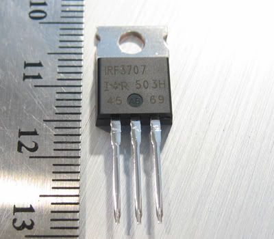
While there are several MOSFETs which satisfy the criteria above to different degrees, we decided to start with one which has already been tested by the Filipino airsoft community as discussed at this thread at FilAirsoft.com. The MOSFET chosen was the International Rectifier IRF3707:
Attribute Value
Vds 30V
Id 62A
Pd 87W
Rds(on) Max 12.5 m-ohm
Full datasheet here: IRF3707 DataSheet
The IRF3707 by International Rectifier can cope with a Vds of 30 volts, well beyond all typical airsoft power sources. The rated continuous current handling capacity of 62 amps also provides plenty of headroom, while the rated 87W power dissipation is right at the recommended value. Lastly, the 12.5 milli-ohms of resistance is quite small and well suited for airsoft applications.
Other Supplies
Several other parts and supplies are needed for installation of a MOSFET:
10k - 30k ohm resistor (1)
100 ohm resistor (1)
20 gauge braided wire for extending stock wiring*
24 gauge or smaller gauge braided wire to act as "gate" wire*
heat shrink wrap*
small PC board*
solder and soldering iron
wire strippers
multimeter*
*braided wires are recommended for their increased flexibility.
*the gate wire should be kept to a small gauge so as to fit in the limited wiring paths of the mechbox. Since little current flows through the gate, smaller gauge wire is not a hinderance to mechbox performance.
*heatshrink in sizes for the wires chosen are recommended to properly insulate junctions.
*a small PC board is recommended for mounting of electrical components.
*a multimeter is recommended for troubleshooting in case of problems.
Stock Schematics
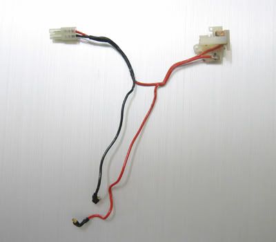
The stock wiring of an AEG mechbox has 1 conduction path. Using the positive current flow convention, current flows from the battery positive terminal through to the trigger contacts via the red wire, then to the selector plate, then down to the motor, and finally back to the battery through the black wire.
We can reduce the stock wiring to a simple schematic representation:
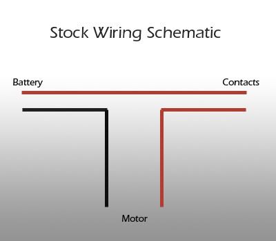
Wiring Schematic
The MOSFET must be installed such that when the trigger and selector plate contacts are closed, a large positive voltage is applied to the Gate pin relative to the Source pin. Additionally, the MOSFET drain and source pins must be placed in series with the conduction path of the motor, thus allowing or disallowing current to flow from battery to motor.
The nature of the MOSFET Gate is capacitative, while the Source and Drain are inductive. These traits lead to a few additional concerns that must be addressed for the MOSFET to function properly as an AEG switch.
Problem 1: Gate Capacitance
The Gate pin of the MOSFET behaves similarly to a very small capacitor, storing charge and retaining its charged state if it is not discharged. This is an undesirable condition, as it means that once we turn on the MOSFET, it will remain on unless we explicitly discharge the Gate. Simply opening the trigger and selector contacts will not accomplish this; a discharge path to the negative battery terminal must be provided for the Gate pin. Additionally, the path must be properly loaded with a resistor so as to prevent excess current flow throught the discharge path, in essence creating a short circuit around the MOSFET.
Problem 2: L-C "Ringing"
Inductor-Capacitor circuits can be induced to oscillate under certain condtions, and this is also the case with MOSFETs. Oscillations, or "ringing" can be prevented by introducing a dampener into the system, such as a small value resistor added in series to the Gate. The resistor slows down the charge and discharge of the MOSFET Gate, reducing the likelihood of oscillation. The resistor value must be kept low however, or risk reducing MOSFET switching efficiency and generating excess heat.
Following all the constraints above, a schematic can be drawn representing the proper wiring of a MOSFET:

In the schematic, a new wire (green) has been added to the stock wiring schematic. The original red wire going to the trigger contact has been removed and resoldered to the "lower" selector plate contact red wire. The new green wire, is now soldered to the original trigger contact position, providing a path to the MOSFET gate pin. When the trigger and selector contacts close, positive charge flows from the battery to the red wire, through the contacts, then to the green wire, which terminates at the Gate. This allows a positive charge to build at the Gate and turn the MOSFET "on". Since the motor black wire is now interrupted by the MOSFET, current will only flow through the motor if the MOSFET is "on", which can only occur if the trigger and selector plate contacts are closed. A discharge path with a 30k ohm resistor has been added between the Gate and Source pins, and a small 100 ohm resistor has been added in series with the Gate pin. When the trigger or selector contact switch is broken, the Gate pin discharges through the 30k ohm resistor back to the battery negative terminal, effectively turning the MOSFET "off". Although larger resistances for the discharge resistor and smaller resistances for the Gate resistor can be used to increase the efficiency of the MOSFET, we chose to stick with known working solutions referenced from the Filipino airsoft community* for the purposes of this article.
*readers RiotSC of California and johnyew of Hong Kong have notified me that the stated resistor values did not originate from the Filipino airsoft board but instead came from this article at a Japanese airsoft site called "Kiss in the Dark".
Installation Instructions
Step 1: Disassemble Mechbox and Remove Switching Assembly
The switching assembly is held in place by only 1 screw. Once the screw is removed, the entire assembly can be removed easily.
Step 2: Desolder/Resolder Trigger Contact Wire
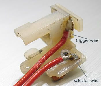
Once the switch assembly has been removed, desolder the "trigger wire" and resolder it to the "selector wire". It is advised that a heatsink clamp is used or to remove the metal contacts from the plastic assembly prior to soldering so as to avoid melting of the switching assembly.
Step 3: Add Gate Wire
Measure a long lenth of thin 24 gauge wire and solder one end to the trigger contact where the trigger wire was removed from in Step 2. This wire will serve as your gate wire, and should be routed through the mechbox following the wiring channels and out the back.
Step 4: Mount MOSFET and Gate Resistor
Mount the MOSFET on the small PC board by poking the 3 pins through the holes on the surface of the board. Select a position on the board adjacent to the gate pin, and mount and solder one end of the 100 ohm gate resistor to the pin.
Step 5: Mount Discharge Resistor
Select a position close to gate pin at one end and the source pin at the other, and mount and solder the 30k discharge/pull-down resistor, with one end to gate and the other to source. Be sure to leave enough space near the source pin soldering another wire in the next step.
Step 6: Solder Wiring
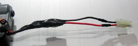
Solder the gate wire to the unsoldered end of the 100 ohm gate resistor to complete the gate connection. Cut the negative battery to mechbox wire (black wire) and solder the mechbox end to the drain pin. Solder the battery connector end of the black wire to the source pin. If the wiring is not long enough, extend the wires using 20 gauge braided wire.
Completed Installation:
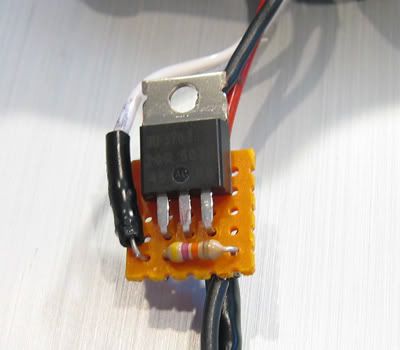
Step 7: Testing Procedure
Set a multimeter to measure DC voltage, and connect the probes to the 2 motor contacts on, positive to red and negative to black. Next, connect your battery to the battery connector. The multimeter should show a miniscule voltage, or zero. Put the selector plate to the semi or full-auto position, and squeeze the trigger. When the trigger is squeezed, the multimeter should show the full voltage of your battery. Next, let go of the trigger. The reading should now instantly fall back down close to zero.
If your circuit passes the above test, the installation is successful and you are ready for a live fire test. It is recommended that the entire circuit board is wraped with electrical tape or sealed with RTV to protect against environmental factors.
Documented Gains
Using the AEG Audio Analysis method, we measure rate of fire of the AEG mechbox before and after installation of the MOSFET. Using solid state switching should in theory improve the rate of fire by reducing the resistance of the system, since the contact switches are no longer part of the main conduction path. The gain should be particularly evident in heavy current drain applications.
The Test Platform
To test the possible gains of installing a MOSFET, we used our test platform G3 SG1 mechbox with the following mechbox modifications.
Systema M120 spring
Systema aluminum piston
Systema polycarb piston head
Systema spring guide with bearing
Prometheus high-speed gears
Systema metal bushings
All rate of fire results were measured using an 8.4v 1800mah battery after a full peak charge.
Battery Voltage Average Rate of Fire Percentage Increase
Stock 9.84v 960.85
IRF3707 9.78v 1048.54 9.1%
STD50NH02 9.78v 1097.56 14.2%
The mechbox configuration with M120 spring and high-speed gears presents a large torque demand for the motor, which in turn places a large current drain on the system, as discussed in Gearbox Science I. The use of a MOSFET in this configuration showed a 9.1% increase in measured rate of fire, which is relatively significant. During operation, the MOSFET began to heat up significantly, but did not fail.
As a side experiment, a more efficient DC-DC converter MOSFET made by STMicroelectronics was soldered into the circuit replacing the IRF3707. The STD50NH02 MOSFET was able to achieve a larger 14.2% gain in rate of fire, but due to its small package size and low power dissipation rating of only 60 watts, could not handle the heat generated by the system. The MOSFET failed after several tests, internally shorting the gate and source pins.
Conclusion
The results from testing with MOSFETs show that there are measureable rate of fire gains when using solid state switching, and this is certainly beneficial in and of itself. However, the tests do not show the primary benefit of removing large currents from the contacts of the AEG mechbox: the reduction of arcing and subsequent wear of the contacts. In applications where large currents are involved, the addition of a MOSFET to the mechbox should always be considered.
In our test application, we used the IRF3707 as suggested by previous successes from the Asian airsoft community. While the MOSFET performed admirably in our tests, it nevertheless exhibited significant heating during operation. The MOSFET in our test did not fail, although it is quite evident that the power dissipation rating of the IRF3707 is very near capacity. As such, we recommend the use of MOSFETs with Pd ratings higher than the 87W rating of the IRF3707, especially in situations more demanding than our test configuration.
Addendum
*reader johnyew of Hong Kong has suggested in this thread on our forums that due to a typo, the original intended MOSFET noted at FilAirsoft.com was the IRF3703, which features a significantly higher power disspiation rating of 230 watts. He also suggests the use of IRL1404, a less expensive MOSFET which features a Pd rating of 200 watts.
taken from © 2005 AirsoftMechanics.com
Introduction:
The key innovation of the Automatic Electric Gun is the introduction of an electrically powered firing mechanism, simultaneously improving superficial realism and reducing the cost of ownership of airsoft guns. Although the use of electricity as an energy source is arguably a step forward in the evolution of the AEG, Tokyo Marui nevertheless decided to stay with a completely mechanical fire control mechanism, employing open contacts at the trigger and selector plate to switch the main conduction path. While there are certainly quantifiable production cost advantages to such a design, there are also decided disadvantages especially when higher voltage sources are used. In this guide, we present one solution to the disadvantages of open contact switches by using solid state switching via metal-oxide semiconductor field effect transistors (MOSFETs), and show a measureable improvement in rate of fire resulting from the modification.
What's Wrong With Contact Switches?
Open contact switches, while often simple and cost effective, presents several drawbacks especially in high voltage applications with inductive loads. The closing of the contacts can result in arcing when high voltages are involved, causing pitting and accelerated corrosion of the contact surfaces. Additionally, when an inductive load such as an AEG motor is de-energized via an opening contact switch, further arcing can occur due to "back EMF" generated by the inductor's attempt to maintain current flow. The combination of these factors contributes to the gradual degradation of the contact surfaces, reducing their current carring capacity, hence hindering optimal AEG performance. This condition, commonly known in airsoft terminology as "burning out the contacts", can be easily remedies through the use of solid state switching ICs such as MOSFETs.
Why MOSFETs
Metal-oxide semiconductor field-effect transistors, or MOSFETs for short, are transistors designed to switch large currents based on gate voltage. Unlike regular BJT transistors, MOSFETs do not require current flow through the gate and are instead switched on the voltage applied to the gate. MOSFETs are also extremely efficient, making them suitable for switching of the large currents involved in an AEG. Typical MOSFETs have 3 pins: Source, Drain, and Gate, abbreviated "S", "D", and "G" respectively. When a positive charge is allowed to accumulate at the Gate pin, the MOSFET allows current to flow between the Drain and Source pins. Conversely, if the charge at the Gate pin is discharged, the MOSFET becomes an extremely large resistor, preventing current flow between Drain and Source. In this way, the MOSFET acts as a solid state switch, turning current on and off based on voltage at the gate.
Using MOSFETs in an AEG isolates the contact switches from the main conduction path, allowing current to flow directly to the motor without encountering the added resistance of the contacts. Additionally, with the primary current isolated, the trigger and selector plate contacts are not subject to the detriments of arcing due to the inductive load presented by the motor. This effectively eliminates the prospect of burned or melted contacts when very high currents are used.
The numerous benefits of incorporating MOSFETs into AEG fire control have long been explored by the Japanese airsoft community, such as this excellent article at "Gun Engineer". Building upon their experiences, we explore the installation of a MOSFET on our test platform G3 SG1 and document any gains which result.
Which MOSFET?
Selecting the right MOSFET for airsoft is a critical step, and it is governed by matching the rated operating specifications of the MOSFET to the expected operating conditions of the mechbox. The specifications of value are maximum Voltage Drain To Source (Vds), maximum continuous Current Drain (Id), maximum Power Dissipation (Pd), and Resistance Drain to Source On (Rds(on)).
Maximum Voltage Drain to Source (Vds):
MOSFETs are extremely sensitive to overvoltage, requiring that the maximum Vds not be exceeded. Since AEG power sources rarely exceed 15 volts even on a full charge, a MOSFET with a Vds rating greater than 15V is required.
Maximum Continuous Current Drain (Id)
Upgraded AEGs often place a heavy current drain on the battery, and a proper MOSFET must be selected which is capable of switching the current. Typical AEGs can exhibit current drains up to about 20 amps, while upgraded AEGs can demand as much as 40 amps. When selecting for the proper Id, it is best to err on the side of caution and utilize a MOSFET with plenty of headroom in Id. It is also important to note that we are interested in the maximum continuous current rating of the MOSFET, not the pulsed rating (Idm), which is typically much much higher.
Maximum Power Dissipation (Pd)
While MOSFETs are highly efficient, there are still inevitable switching losses which must be dissipated by the MOSFET in the form of heat. The maximum Pd rating is the amount of power the MOSFET is designed to handle and properly dissipate without suffering failure, and it is closely related to the external packaging design of the MOSFET. Those which use larger packaging form factors, such as a TO-220AB, are typically able to handle higher power dissipation duties than those using the much more compact I-Pak packaging. Much like the Id rating of the MOSFET, it is best to have plenty of headroom in Pd. Drawing from the experiences of the Japanese airsoft community, it is recommended that a Pd rating of atleast 80 watts is selected. Since there is little space in the typical airsoft rifle for a MOSFET heatsink, it is also recommended that the largest packaging available is selected to help dissipate heat.
Resistance Drain to Source On (Rds(on))
Rds(on) is a measure of the resistance the MOSFET presents to the flowing current during the "on" state. The lower this number is the better, as it means the MOSFET allows more current through with less heat loss.
While there are several MOSFETs which satisfy the criteria above to different degrees, we decided to start with one which has already been tested by the Filipino airsoft community as discussed at this thread at FilAirsoft.com. The MOSFET chosen was the International Rectifier IRF3707:

Attribute Value
Vds 30V
Id 62A
Pd 87W
Rds(on) Max 12.5 m-ohm
Full datasheet here: IRF3707 DataSheet
The IRF3707 by International Rectifier can cope with a Vds of 30 volts, well beyond all typical airsoft power sources. The rated continuous current handling capacity of 62 amps also provides plenty of headroom, while the rated 87W power dissipation is right at the recommended value. Lastly, the 12.5 milli-ohms of resistance is quite small and well suited for airsoft applications.
Other Supplies
Several other parts and supplies are needed for installation of a MOSFET:
10k - 30k ohm resistor (1)
100 ohm resistor (1)
20 gauge braided wire for extending stock wiring*
24 gauge or smaller gauge braided wire to act as "gate" wire*
heat shrink wrap*
small PC board*
solder and soldering iron
wire strippers
multimeter*
*braided wires are recommended for their increased flexibility.
*the gate wire should be kept to a small gauge so as to fit in the limited wiring paths of the mechbox. Since little current flows through the gate, smaller gauge wire is not a hinderance to mechbox performance.
*heatshrink in sizes for the wires chosen are recommended to properly insulate junctions.
*a small PC board is recommended for mounting of electrical components.
*a multimeter is recommended for troubleshooting in case of problems.
Stock Schematics
The stock wiring of an AEG mechbox has 1 conduction path. Using the positive current flow convention, current flows from the battery positive terminal through to the trigger contacts via the red wire, then to the selector plate, then down to the motor, and finally back to the battery through the black wire.

We can reduce the stock wiring to a simple schematic representation:

Wiring Schematic
The MOSFET must be installed such that when the trigger and selector plate contacts are closed, a large positive voltage is applied to the Gate pin relative to the Source pin. Additionally, the MOSFET drain and source pins must be placed in series with the conduction path of the motor, thus allowing or disallowing current to flow from battery to motor.
The nature of the MOSFET Gate is capacitative, while the Source and Drain are inductive. These traits lead to a few additional concerns that must be addressed for the MOSFET to function properly as an AEG switch.
Problem 1: Gate Capacitance
The Gate pin of the MOSFET behaves similarly to a very small capacitor, storing charge and retaining its charged state if it is not discharged. This is an undesirable condition, as it means that once we turn on the MOSFET, it will remain on unless we explicitly discharge the Gate. Simply opening the trigger and selector contacts will not accomplish this; a discharge path to the negative battery terminal must be provided for the Gate pin. Additionally, the path must be properly loaded with a resistor so as to prevent excess current flow throught the discharge path, in essence creating a short circuit around the MOSFET.
Problem 2: L-C "Ringing"
Inductor-Capacitor circuits can be induced to oscillate under certain condtions, and this is also the case with MOSFETs. Oscillations, or "ringing" can be prevented by introducing a dampener into the system, such as a small value resistor added in series to the Gate. The resistor slows down the charge and discharge of the MOSFET Gate, reducing the likelihood of oscillation. The resistor value must be kept low however, or risk reducing MOSFET switching efficiency and generating excess heat.
Following all the constraints above, a schematic can be drawn representing the proper wiring of a MOSFET:

In the schematic, a new wire (green) has been added to the stock wiring schematic. The original red wire going to the trigger contact has been removed and resoldered to the "lower" selector plate contact red wire. The new green wire, is now soldered to the original trigger contact position, providing a path to the MOSFET gate pin. When the trigger and selector contacts close, positive charge flows from the battery to the red wire, through the contacts, then to the green wire, which terminates at the Gate. This allows a positive charge to build at the Gate and turn the MOSFET "on". Since the motor black wire is now interrupted by the MOSFET, current will only flow through the motor if the MOSFET is "on", which can only occur if the trigger and selector plate contacts are closed. A discharge path with a 30k ohm resistor has been added between the Gate and Source pins, and a small 100 ohm resistor has been added in series with the Gate pin. When the trigger or selector contact switch is broken, the Gate pin discharges through the 30k ohm resistor back to the battery negative terminal, effectively turning the MOSFET "off". Although larger resistances for the discharge resistor and smaller resistances for the Gate resistor can be used to increase the efficiency of the MOSFET, we chose to stick with known working solutions referenced from the Filipino airsoft community* for the purposes of this article.
*readers RiotSC of California and johnyew of Hong Kong have notified me that the stated resistor values did not originate from the Filipino airsoft board but instead came from this article at a Japanese airsoft site called "Kiss in the Dark".
Installation Instructions
Step 1: Disassemble Mechbox and Remove Switching Assembly
The switching assembly is held in place by only 1 screw. Once the screw is removed, the entire assembly can be removed easily.

Step 2: Desolder/Resolder Trigger Contact Wire
Once the switch assembly has been removed, desolder the "trigger wire" and resolder it to the "selector wire". It is advised that a heatsink clamp is used or to remove the metal contacts from the plastic assembly prior to soldering so as to avoid melting of the switching assembly.
Step 3: Add Gate Wire
Measure a long lenth of thin 24 gauge wire and solder one end to the trigger contact where the trigger wire was removed from in Step 2. This wire will serve as your gate wire, and should be routed through the mechbox following the wiring channels and out the back.
Step 4: Mount MOSFET and Gate Resistor
Mount the MOSFET on the small PC board by poking the 3 pins through the holes on the surface of the board. Select a position on the board adjacent to the gate pin, and mount and solder one end of the 100 ohm gate resistor to the pin.
Step 5: Mount Discharge Resistor
Select a position close to gate pin at one end and the source pin at the other, and mount and solder the 30k discharge/pull-down resistor, with one end to gate and the other to source. Be sure to leave enough space near the source pin soldering another wire in the next step.
Step 6: Solder Wiring
Solder the gate wire to the unsoldered end of the 100 ohm gate resistor to complete the gate connection. Cut the negative battery to mechbox wire (black wire) and solder the mechbox end to the drain pin. Solder the battery connector end of the black wire to the source pin. If the wiring is not long enough, extend the wires using 20 gauge braided wire.
Completed Installation:

Step 7: Testing Procedure
Set a multimeter to measure DC voltage, and connect the probes to the 2 motor contacts on, positive to red and negative to black. Next, connect your battery to the battery connector. The multimeter should show a miniscule voltage, or zero. Put the selector plate to the semi or full-auto position, and squeeze the trigger. When the trigger is squeezed, the multimeter should show the full voltage of your battery. Next, let go of the trigger. The reading should now instantly fall back down close to zero.
If your circuit passes the above test, the installation is successful and you are ready for a live fire test. It is recommended that the entire circuit board is wraped with electrical tape or sealed with RTV to protect against environmental factors.

Documented Gains
Using the AEG Audio Analysis method, we measure rate of fire of the AEG mechbox before and after installation of the MOSFET. Using solid state switching should in theory improve the rate of fire by reducing the resistance of the system, since the contact switches are no longer part of the main conduction path. The gain should be particularly evident in heavy current drain applications.
The Test Platform
To test the possible gains of installing a MOSFET, we used our test platform G3 SG1 mechbox with the following mechbox modifications.
Systema M120 spring
Systema aluminum piston
Systema polycarb piston head
Systema spring guide with bearing
Prometheus high-speed gears
Systema metal bushings
All rate of fire results were measured using an 8.4v 1800mah battery after a full peak charge.
Battery Voltage Average Rate of Fire Percentage Increase
Stock 9.84v 960.85
IRF3707 9.78v 1048.54 9.1%
STD50NH02 9.78v 1097.56 14.2%
The mechbox configuration with M120 spring and high-speed gears presents a large torque demand for the motor, which in turn places a large current drain on the system, as discussed in Gearbox Science I. The use of a MOSFET in this configuration showed a 9.1% increase in measured rate of fire, which is relatively significant. During operation, the MOSFET began to heat up significantly, but did not fail.
As a side experiment, a more efficient DC-DC converter MOSFET made by STMicroelectronics was soldered into the circuit replacing the IRF3707. The STD50NH02 MOSFET was able to achieve a larger 14.2% gain in rate of fire, but due to its small package size and low power dissipation rating of only 60 watts, could not handle the heat generated by the system. The MOSFET failed after several tests, internally shorting the gate and source pins.
Conclusion
The results from testing with MOSFETs show that there are measureable rate of fire gains when using solid state switching, and this is certainly beneficial in and of itself. However, the tests do not show the primary benefit of removing large currents from the contacts of the AEG mechbox: the reduction of arcing and subsequent wear of the contacts. In applications where large currents are involved, the addition of a MOSFET to the mechbox should always be considered.
In our test application, we used the IRF3707 as suggested by previous successes from the Asian airsoft community. While the MOSFET performed admirably in our tests, it nevertheless exhibited significant heating during operation. The MOSFET in our test did not fail, although it is quite evident that the power dissipation rating of the IRF3707 is very near capacity. As such, we recommend the use of MOSFETs with Pd ratings higher than the 87W rating of the IRF3707, especially in situations more demanding than our test configuration.
Addendum
*reader johnyew of Hong Kong has suggested in this thread on our forums that due to a typo, the original intended MOSFET noted at FilAirsoft.com was the IRF3703, which features a significantly higher power disspiation rating of 230 watts. He also suggests the use of IRL1404, a less expensive MOSFET which features a Pd rating of 200 watts.

